
HVAC
Why VRF Diagnostics Demand a Systems-Level Approach
Why VRF Diagnostics Demand a Systems-Level Approach
Understanding the Shift from Component-Level to System-Level Thinking
A Variable Refrigerant Flow system operates as an integrated ecosystem, not a collection of independent components. While the basic refrigeration principles remain the same, the way these systems regulate themselves is fundamentally different. You have a variable-speed compressor constantly adjusting output, dozens of sensors feeding data to control boards, electronic expansion valves responding in real-time, and a communication network tying it all together.
VRF systems have the ability to self-diagnose maintenance needs, but that self-diagnosis is only as good as your ability to interpret what the system is telling you. The fault code you see? That's a symptom. Your job is to diagnose the underlying cause—and that requires a methodical, system-wide approach.
The days of relying solely on pressure-temperature charts and manifold gauges are over. Not because those tools aren't useful, but because they only show you part of the picture. In a VRF system, everything affects everything else, and understanding those relationships is what separates efficient diagnostics from hours of trial-and-error troubleshooting.
Why VRF Systems Require a Different Diagnostic Framework
Think of a conventional HVAC system like a simple machine—you have fixed operating parameters, static refrigerant flow, and predictable behavior. A VRF system, on the other hand, is more like a living organism that constantly adapts to changing conditions. VRF systems use a refrigerant as the working fluid in direct expansion air conditioning systems, but with variable-speed technology that adjusts capacity based on real-time demand from multiple zones.
The pressures you measure today won't be the same tomorrow, even under identical loads, because the system is optimizing efficiency by modulating compressor speed, adjusting EEV positions, and balancing refrigerant distribution across multiple indoor units. That's why single data points—like suction pressure or superheat—can be misleading without understanding the broader operational context.
This is similar to how modern HVAC contractors are leveraging technology to improve operational efficiency—you need to see the complete picture, not just isolated data points.
Building Your VRF Diagnostic Toolkit
Success with VRF diagnostics starts with having the right tools. Here's what you actually need:
The Manufacturer-Specific Service Tool (Non-Negotiable)
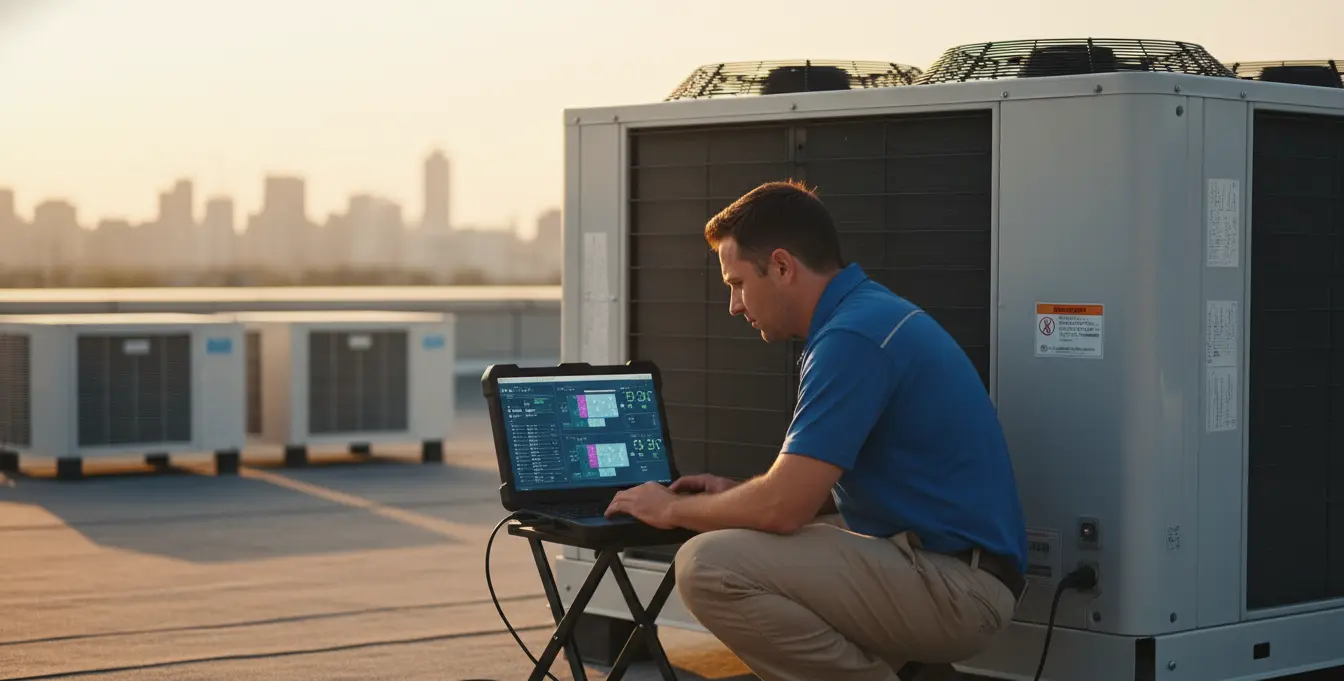
Whether it's laptop-based software or a handheld diagnostic device, this tool connects directly to the outdoor unit's control board and gives you access to the system's operational data. You can view real-time sensor readings, review historical fault logs, monitor compressor frequency, check EEV positions, and analyze communication status between units.
Without this tool, you're making educated guesses instead of data-driven diagnoses. Every major VRF manufacturer provides these diagnostic tools, and they're constantly updated to reflect firmware improvements and new diagnostic capabilities.
High-Precision Refrigerant Scale
VRF systems are critically charged by design. The indoor and outdoor units must be sized correctly to avoid causing discomfort or equipment damage, and the same precision applies to refrigerant charge. While a residential split system might tolerate being a few ounces off, a VRF system serving multiple zones can show performance degradation from charge variances as small as 2-3 ounces.
Invest in a scale with 0.05 lb resolution minimum. This isn't about being overly precise—it's about maintaining system efficiency and reliability over the long term.
Digital Manifold with Superheat/Subcooling Capability
Even though VRF systems operate with constantly changing pressures, traditional refrigeration principles still apply. You need to verify that the system is achieving proper superheat and subcooling at different load conditions. A quality digital manifold lets you monitor these values in real-time and cross-reference them with data from your service tool.
The Pre-Diagnostic Baseline: Setting Yourself Up for Efficient Troubleshooting
Before connecting any diagnostic tools, establish a baseline understanding of the installation and current system state. This methodical approach often reveals problems immediately—or provides critical context for deeper analysis.
Verify Installation Integrity
Many service calls trace back to installation issues. Do a quick but thorough visual inspection: Are refrigerant lines properly insulated and secured with minimal stress on connections? Is the outdoor unit positioned with adequate clearance for airflow and service access? Are condensate lines properly pitched and trapped? Are indoor units mounted level?
Poor installation creates long-term reliability issues. Identifying these problems upfront saves diagnostic time and helps you provide better recommendations to your customers.
Understand the System Controller's Logic
Don't just talk to the customer—interrogate the controller itself. What mode is the system operating in? Are there scheduling conflicts between different zones? Is a master thermostat overriding individual zone settings? Are there simultaneous heating and cooling calls causing the system to cycle between modes?
Design engineers should consider specific procedures and design factors when working with VRF systems, and understanding the control logic is crucial for proper diagnostics. Misconfigured controls are one of the most common sources of performance complaints—and fortunately, one of the easiest to resolve once you know what to look for.
Check Communication Bus Integrity
The communication wiring is the nervous system of a VRF installation. Most manufacturers use a simple 2-wire, non-polarized bus (typically labeled F1/F2 or P/Q). Use your multimeter to verify proper voltage—you should see a fluctuating DC voltage, typically between 24-48V depending on the manufacturer.
A dead voltage or steady DC reading indicates a communication failure somewhere in the system. This could be damaged wiring, a failed indoor unit control board, improper termination, or a short circuit. Communication issues cause cascading problems throughout the system, so resolving these first often eliminates multiple fault codes at once.
Analyzing System Data: The Heart of VRF Diagnostics
Once you've connected your manufacturer's service tool, resist the urge to immediately start making changes. Your first job is to understand the system's current operating state and identify patterns in the data.
Step 1: Capture a Complete System Snapshot
Document everything before touching anything. Record active fault codes, but more importantly, note the operational parameters: How many indoor units are online and calling? What's the outdoor ambient temperature according to the system's sensor? What frequency is the compressor running at? What are the current EEV positions?
This baseline snapshot gives you a reference point. As you make diagnostic changes or wait for the system to cycle through different operating modes, you'll be able to see how the system responds and whether you're moving in the right direction.
Step 2: Analyze the Four Key Thermistors
These temperature sensors tell the story of your refrigeration circuit. Focus on these readings from the outdoor unit:
Discharge Temperature: This shows the temperature of refrigerant leaving the compressor. High discharge temperatures (above manufacturer specifications, typically 200-240°F depending on the system) indicate poor heat rejection, potential overcharge, or excessive compression ratios. This is your early warning system for compressor stress.
Suction Temperature: Indicates the temperature of refrigerant returning to the compressor. Abnormally low temperatures suggest liquid refrigerant is making it back to the compressor (floodback condition). High suction temperatures indicate inadequate refrigerant flow or possible undercharge.
Liquid Line Temperature: This reflects how effectively your outdoor coil is rejecting heat. Compare this temperature to outdoor ambient to calculate subcooling. Low subcooling indicates undercharge or poor heat rejection; excessive subcooling suggests overcharge or restricted indoor units.
Outdoor Coil Temperature: Shows condenser performance. Large temperature differences between this sensor and outdoor ambient indicate airflow restrictions, coil fouling, or fan problems.
Step 3: Interpret Electronic Expansion Valve Positions
EEVs are the system's primary method of controlling refrigerant flow to each indoor unit. Their position—reported in pulses ranging from 0 to their maximum (typically 480 or 2000 pulses depending on the valve)—reveals what the system is trying to accomplish:
EEVs Wide Open (near maximum pulses): The system is requesting maximum refrigerant flow but isn't getting enough. Check for undercharge, liquid line restrictions, or outdoor unit capacity issues.
EEVs Nearly Closed (near minimum pulses): Indicates the system is restricting flow because of overcharge, inadequate airflow at the indoor unit (check filters), or temperature sensor issues.
Erratic EEV Behavior: Valves constantly hunting between positions suggest unstable superheat control, often caused by intermittent refrigerant flow problems, sensor drift, or system instability from incorrect refrigerant charge.
Step 4: Correlate Data Points to Understand Root Causes
This is where diagnostic expertise separates efficient technicians from those who spend hours chasing symptoms. Individual data points only have meaning in context.
Example: You measure a suction pressure of 90 PSI. Is that a problem? It depends. If the compressor is running at its minimum frequency (30 Hz) with only one small indoor unit calling for cooling, that pressure might be perfectly normal for the load condition. But if that same 90 PSI reading occurs while the compressor is running at 100 Hz with five indoor units calling for full cooling, you have a serious refrigerant starvation problem.
Don't just read the numbers—understand the relationships between compressor speed, active indoor units, outdoor ambient conditions, and EEV positions. That's how you diagnose root causes instead of replacing parts based on fault codes.
This methodical approach mirrors how successful contractors handle complex HVAC system quoting and project management—breaking down complexity into logical, analyzable components.
Leveraging Technology for More Efficient Service Operations
The diagnostic work you're doing on VRF systems represents high-value service—but only if you're not drowning in administrative overhead. The data you collect, the service reports you generate, and the maintenance schedules you manage all require time that should be spent on billable work.
This is where Trade Agent helps VRF specialists build more efficient, profitable service businesses:
When you're managing multiple commercial VRF installations across different properties, the administrative burden scales quickly. Creating detailed service reports with diagnostic findings, scheduling preventive maintenance visits, generating itemized invoices with parts and labor—all of this eats into the profitability of your high-value service work.
Trade Agent's platform is built for HVAC contractors who handle complex commercial systems like VRF. You can document service calls while you're still on-site, using your phone to capture photos of diagnostic screens, system data, and work performed. Our AI processes this information to generate professional service reports that clients understand—explaining technical findings in clear language while maintaining all the detail you need for proper documentation.
The system learns your pricing for common VRF maintenance contracts and repair work, making it faster to quote seasonal tune-ups, emergency service calls, or system commissioning. For contractors building a VRF service business—where jobs are higher-margin but require meticulous documentation—this means you can scale your commercial work without scaling your back-office time.
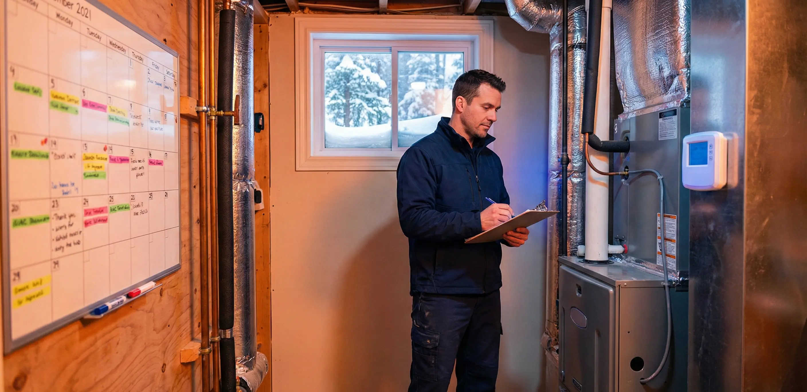
Building Long-Term Reliability Through Preventive Maintenance
VRF systems typically have a 10-year full warranty, and annual preventive maintenance is easier to perform and usually much less expensive than for conventional HVAC systems. This creates an excellent opportunity for contractors to build recurring revenue streams while ensuring system reliability for your customers.
Effective VRF preventive maintenance goes beyond filter changes. You're analyzing system performance trends, catching minor issues before they become major failures, and documenting system behavior over time. This historical data becomes invaluable for diagnosing intermittent problems and optimizing system performance.
The most successful VRF specialists don't just fix problems—they prevent them. That requires systematic record-keeping, scheduled maintenance, and proactive communication with property managers and building owners.
From Troubleshooter to System Specialist
Mastering VRF diagnostics is about developing a systems-level mindset. The basic principles of air conditioning apply to VRF systems, but there are differences that a service company or technician needs to understand and be knowledgeable in handling.
You're not just responding to fault codes—you're analyzing how dozens of components interact, how the system adapts to changing loads, and how long-term performance trends indicate potential issues before they become failures.
This expertise is what allows you to command premium pricing for VRF service work. You're not a parts-changer; you're a system diagnostician who understands the cause-and-effect relationships that determine system performance and reliability.
According to ASHRAE Guideline 41-2023, proper design, installation, and commissioning procedures are essential for VRF system performance. Your diagnostic capabilities ensure these systems continue operating efficiently long after installation is complete.
Frequently Asked Questions
Q: Can I diagnose VRF systems without manufacturer-specific diagnostic tools?
No. Attempting VRF diagnostics without the proper service tool is like trying to balance a complex equation without knowing all the variables. You might identify obvious failures, but you'll miss the operational data that reveals root causes and allows for efficient troubleshooting.
Q: How often should VRF systems receive preventive maintenance?
Annual preventive maintenance for VRF systems is typically easier to perform and much less expensive than for conventional HVAC systems. However, indoor unit filters should be checked quarterly in commercial applications, and systems in harsh environments may benefit from semi-annual inspections of outdoor coils and refrigerant connections.
Q: What causes most VRF system failures?
Communication failures between indoor and outdoor units are extremely common, usually stemming from installation issues like improper wiring, damaged cables, or termination errors. The second most frequent issue is refrigerant-related problems—either incorrect charge during installation or leaks at brazed connections that weren't properly inspected.
Q: Do I need specialized training to service VRF systems?
Yes. ASHRAE Standard 15 classifies VRF systems as direct systems and high-probability systems, meaning they have specific safety requirements and installation standards. More importantly, each manufacturer's control logic and diagnostic procedures are different. Manufacturer-specific training significantly improves your diagnostic efficiency.
Q: How should I price VRF diagnostic work compared to standard service calls?
VRF diagnostics command premium pricing due to the specialized knowledge, tools, and systematic analysis required. Many contractors charge 1.5-2x their standard service rate for VRF work, with additional diagnostic fees for complex troubleshooting. Just as accurate labor estimating is critical for commercial electrical work, proper pricing for VRF service protects your margins and reflects the value you provide.
Build a More Efficient VRF Service Business
You've invested in the training, tools, and expertise to become a VRF specialist. Don't let administrative work undermine the profitability of your high-value service calls.
Try Trade Agent free and see how getting 2 days back in your week allows you to take on more profitable VRF maintenance contracts.
Create detailed service reports in under 2 minutes. Schedule recurring maintenance automatically. Generate professional invoices while you're still on-site. See why HVAC contractors specializing in commercial systems are using Trade Agent to build more efficient, more profitable businesses.


Similar posts
Book Your Demo


